Introduction
Typical high-energy particle physics experiments today employ
large-scale silicon tracking detectors. The mounting precision
with which the modules are mounted inside the tracking device
is typically worse than their intrinsic measurement
resoution. In order not to loose information, the module
position needs to be measured from data with higher precision
than the intrinsic resolution. This is called
"alignment". However, the recipe is not constrained
to silicon detector alignment and can be applied to other
tracking devices easily.
Different methods are available for detector alignment. The
method presented here is based on the Kalman Filter and was
first published in Reference [1]. This software is an
experiment-independent implementation of this algorithm which
can be used under the terms of the GPL and has been published
in Reference [2]. Additionally it contains a complete
simulation of tracks in a silicon tracking device and track
reconstruction. Also tools for data-driven validation and
validation with respect to the input to simulation are
available.
Contents
This project contains a simulation package, the Kalman
alignment algorithm and a validation package. With the
simulation package, one can simulate tracks in a misaligned
detector. The Kalman alignment algorithm can be used to
correct for the misalignment, i.e. compute the alignment
constants. The data-driven validation package can be used to
see the track χ2-improvement after
alignment.
Installation instructions
Start by checking out the code from the subversion repository:
svn co http://svn.hepforge.org/kalmanalignment/tags/release-1.0
Then follow the steps in
the Documentation.
Sample output
The topmost picture on the right shows a misaligned detector
and many tracks traversing the detector. This is a screenshot
from the simulation package.
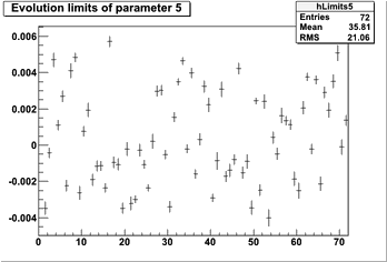
The picture below shows the alignment result for the most
sensitive rotation angle of the detector (gamma) after
alignment. For each detector (72 detectors in total), the
value of the alignment parameter and its error are indicated.
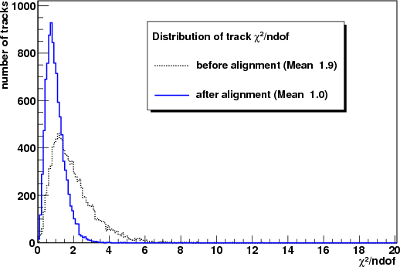
The picture at the bottom is a screenshot from the validation
package, showing the normalized track
χ2-distribution before and after alignment. In
this case, a moderate misalignment was applied. After
alignment, the track χ2-distribution is almost
ideal (mean is close to unity).
|

A heavily misaligned detector with lots of tracks going through
the modules (screenshot from the simulation package).

Determined alignment parameters for the most sensitive rotation angle for each detector.

Normalized χ2-distribution before and after
alignment.
|


